What is an Interferometer and how does it work?
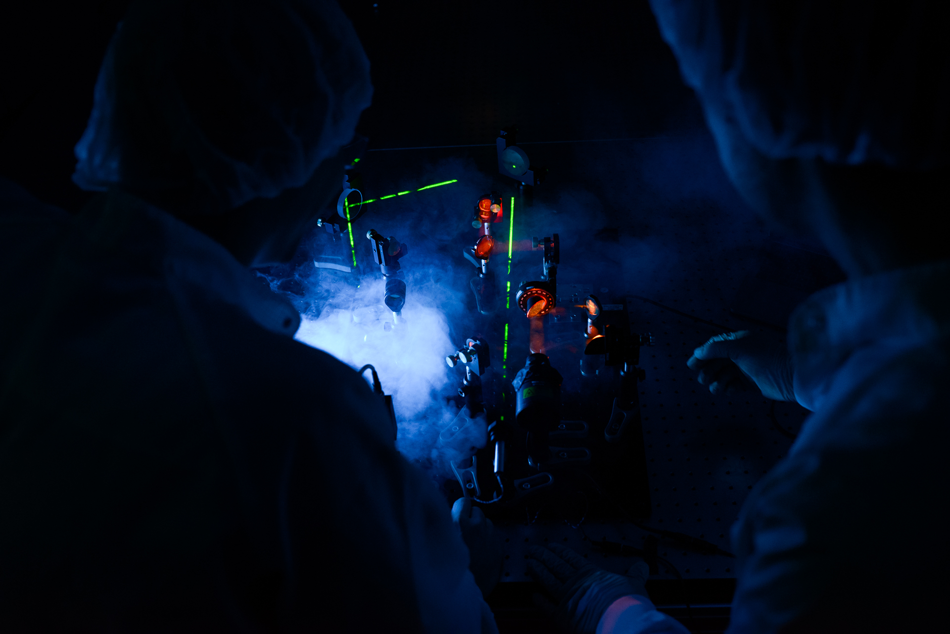
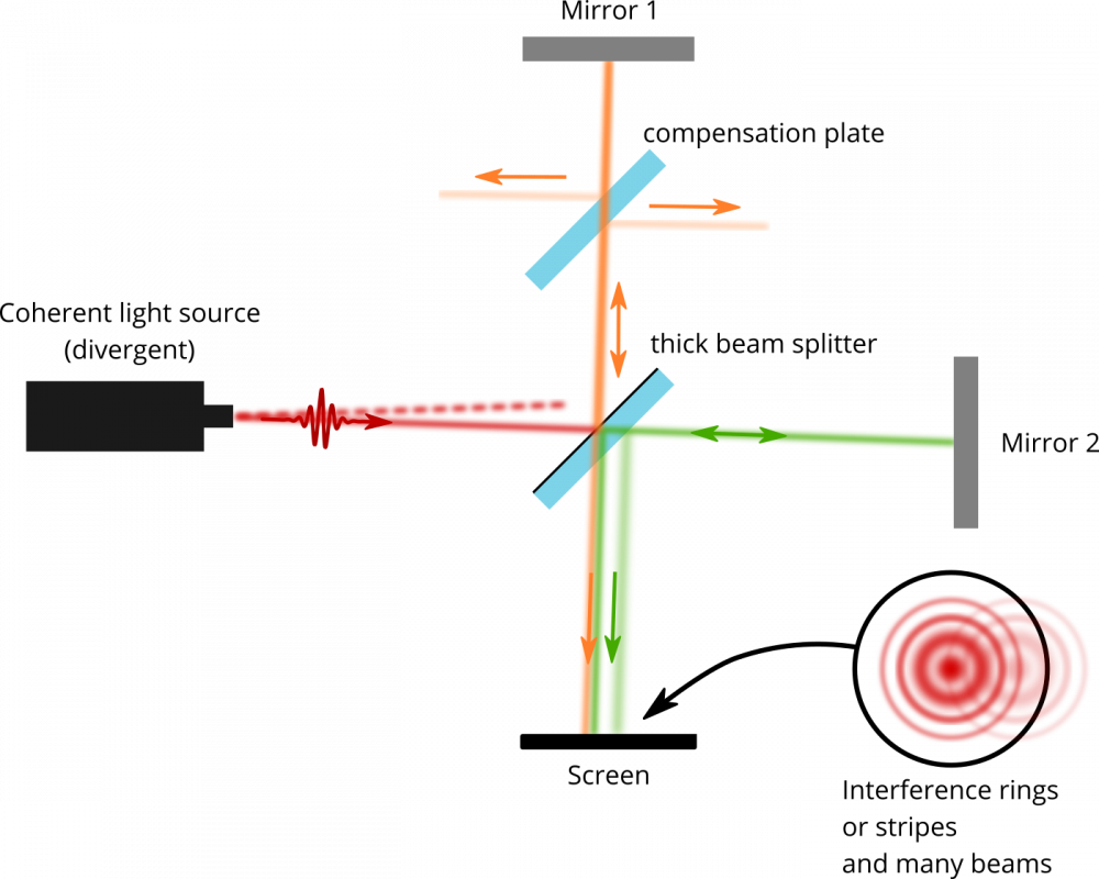
An interferometer is a measurement device that uses coherent light and creates a superposition of two light beams which is called interference. The Michelson Interferometer is a simple type of interferometer which needs only few optical components, is easy to align and thus is widely used for many applications. A sketch of a typical setup is shown in Fig. 1.
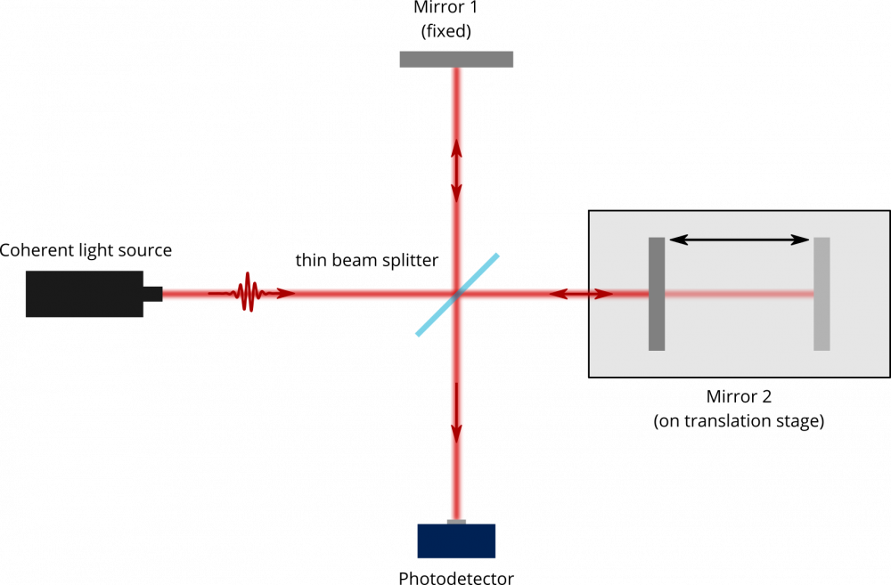
To take advantage of the interference effect a coherent light source is essential. Usually a monochromatic laser is used. Both, continuous wave as well as pulsed lasers can be used.The incoming beam hits a thin beam-splitter and its intensity amplitude is split into two weaker beams. Each of these beams is reflected back to the thin beam splitter by an adjustable mirror, where the beams are combined again. If the phase difference of the two light beams is zero, the two beams will interfere constructively, and a high intensity signal will be measured on the photodetector. In contrast, if the phase difference is half the wavelength of the light the two beams will cancel, and the detector signal will drop to zero. As the phase difference of the two light beams depends on the difference of their optical beam path, slight changes of the distance between one of the mirrors and the beam-splitter result in strong intensity modulations on the photodetector.
The sensitivity of these intensity modulations on the optical delay naturally depends on the wavelength used in the spectrometer. For example, when using a standard Helium-neon alignment laser with wavelength of 633 nm a change in the optical path difference of only 317.5 nm will change the interference signal on the detector from maximum to minimum or vice versa. This illustrates the extreme sensitivity of this measurement technique.
What can I use it for?
Due to its ability to measure changes in the optical pathlength difference of the two interferometer arms with
nanometer precision, interferometers are often used for highly demanding distance measurements and positioning tasks. One of the mirrors is kept fixed and the movement of the other one which is part of the positioning system is monitored by observing changes in the interference pattern.
Another very important application is the
determination of the wavelength of the incoming light. For this purpose, the intensity fluctuations of the interference pattern are monitored while one external arm mirror (e.g. mirror 2 in Fig. 1) is moved and its position is logged. The intensity of the interference can now be plotted over the time difference dt for which the light travelled in both interferometer arms. A Fourier transformation of this time domain trace gives the spectrum of the source.
A typical use case in the laser lab is the determination of the spectrum of a laser source which
was generated in a nonlinear process (e.g. sum-/difference-frequency generation, optical parametric amplification…). Thus, the interferometer is used to tune these processes to give the desired output frequencies.
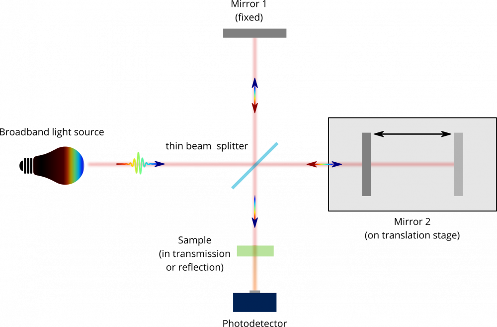
This exact effect is also used in the construction of a spectrometer (cf. Fig 2). Here, usually a broadband light source is used as the input light of the interferometer and a sample is placed in one of its arms after the beam-splitter. By comparing the spectra of the light withand without the sample in place it is possible to observe what wavelengths were absorbed by the light. Depending on the wavelength range, this enables materials analysis by comparison with reference spectra and determination of molecular vibrations.
What parts do I need to build it?
- A Coherent light source in the desired wavelength regime. In case you are using a pulsed laser and / or are working with invisible light (e.g. Infrared) it is highly suggested to use a simple alignment laser for the pre-alignment of the setup. It is much easier to find the interference pattern with visible cw light first and afterwards couple the invisible light on the same path (e.g. via two irises) for a last fine tune.
- An adjustable thin beam-splitter (pellicle) for the wavelength of your laser (ideally R:T = 1:1). If you plan to use a thick beamsplitter see the section below. You will also need a compensation plate.
- Two adjustable mirrors
- A translation stage – if you want to automatically measure spectra of your laser beam a motorized stage is very helpful.
- A screen to display the interference pattern
- A photodetector to quantify the brightness of your interference signal
- A data acquisition system which can display (and record) the output signal of your detector. This could be a simple oscilloscope to start with and/or a data acquisition card / lock-in amplifier to digitize the data.
- A ruler / tape measure to measure the length of the interferometer arms
How do I align it with a thin beamsplitter ?
Aligning a Michelson interferometer is not difficult when following a systematic procedure. The following recipe is based on the design of Fig.1.
- Ensure that your input laser beam is at a constant height above your table and align mirror 2 (which should be in the middle of the translation stage) so that the reflected beam is nearly coming back to the input of the laser and is in line with the axis of the stage. If you don’t know how to efficiently align a translation stage have a look for this tutorial on our website.
- Place the beam-splitter at an angle of 45° in the path and make sure the reflected beam towards mirror 1 keeps its height constant and has an angle of 90° to the incoming beam. Especially if you are working with pulsed lasers this is the moment you really want to make sure that the length of the two arms is equal. So, use your ruler and try to match the distances of the two mirrors from the beam splitter as good as you can.
- For a successful alignment it is very important to note that having both beams overlap back on the beam splitter is necessary but not sufficient. Rather, the two combined beams need to be colinear so that they overlap everywhere between the beam splitter and the photodetector / screen.
The easiest way to align an interferometer is to make sure that both arms retroreflect back on their incident position on the beam splitter independently. If this is the case they must be aligned to each other also after the beam splitter.
Therefore, first block one arm and make sure the reflected beam is retroreflected on the same spot on the beam splitter. To do this it might be helpful to hold a paper with a hole a little smaller than the beam in the path just after the beam splitter. This allows the light from the beam splitter to pass through the middle and the reflected light can be aligned to the hole on the paper.
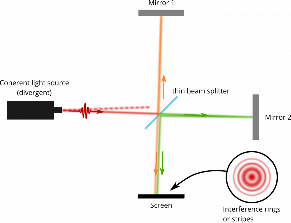
Now repeat this procedure with the other arm. - You can now have a look on the combined beam by placing a screen. Depending on how precisely you did the alignment of the last step you should already see an interference pattern. This pattern might look like circles, or even circle segments / stripes. Since no laser source can produce a perfectly collinear beam, the intrinsic divergence leads to slight changes in the optical path depending on where on the display screen you are looking at. This phenomenon is depicted in Fig. 3. If the divergence of your input light is high or the optical path length of the two arms is not similar, you might want to re-collimate the input beam or use lenses in the arms. This helps to mode match the interfering beams and results in bigger and easily observable interference fringes. If you think there are interference fringes you could check if they are vanishing when you block either arm of the interferometer.
In general, if you see vertical (horizontal) stripes this means the beams are not perfectly aligned in the horizontal (vertical) direction. You can try to compensate for this with mirror 1 (as this is not on a stage you would misalign again). If the stripes are neither horizontal nor vertical probably both horizontal and vertical direction of the beams should be optimized. The interference pattern should get coarser with fewer stripes / rings the better the alignment is.
The aligned interferometer should be very sensitive to mirror movements – so for a He-Ne laser you should get strong intensity fluctuations on the screen even when you only tap one of the mirrors. - In case you are using a pulsed laser, this is the moment to swap your laser source and couple the actual pulsed one into the interferometer. Use two irises to make sure the pulsed laser is matching the beam path of the alignment laser as good as possible. Don’t worry if you do not see an interference pattern on the screen immediately. On top of a good alignment you of course must find the time overlap between the two beams as well. Therefore, you can carefully adjust the stage of mirror 2 while looking for intensity fluctuations on the screen / detector.
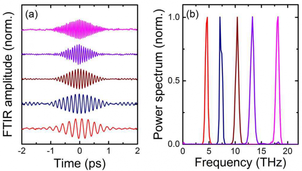
- Once you have everything aligned you can check your interferometer by scanning the stage of mirror 2 while monitoring the output intensity (make sure your detector is in the middle of the interference pattern). Fig. 4a. shows several examples of such interferograms. In this case THz radiation was tuned by changing the difference frequency between the two linearly chirped near-IR pulses. Fourier transformation of the transient electric fields results in the spectra shown in Fig. 4b.
What is the difference in a Michelson Interferometer with a thick beamsplitter ?
If you build a FTIR using a thick (more than lets say 100 um thick) coated beamsplitter you want to use a compensation plate in one of the arms. The coated reflective surface (indicated in black on the beamsplitter in Fig. 5) will be the surface giving you hopefully an ideal 50:50 reflection/transmission ratio and the beamsplitter material itself is without losses for the wavelength you use.
You can imagine that the green beam should have beam passed 3 times through the beamsplitter material thickness (times square root of 2 because of 45 degree incidence). If every passage through the material leads to some dispersion or whatever effects on your pulse it is necessary to introduce the same dispersion in the other interferometer arm also. Therefore you have to add a compensation plate of the same material and thickness as the beamsplitter material so the orange beam will experience the same dispersion.
A thin pellicle beamsplitter on the other hand is so thin that you can take it as negligible and just consider it as a reflective surface without material behind it. The pellicle beamsplitters have the disadvantage of vibration (drum noise) and on top of this pellicle beamsplitters do not exist for all wavelengths with the necessary coating.
How do I align it with a thick beamsplitter ?
Aligning a Michelson interferometer with a thick beamsplitter is not as easy but possible of course when you consider the rules mentioned below. The discussion is based on the design of Fig. 5.
- Follow the steps 1-3 for the thin beamsplitter and do not insert the compensation plate yet. Make sure that the reflections from the mirrors 1 and 2 go back onto the beamsplitter where the respective beams exited the beamsplitter. Especially the beam coming from mirror 2 will exhibit a first reflection on the back surface of the beamsplitter material before entering the material and being reflected at the front surface.
- Be aware that the reflection intensities might not be the same at your visible alignment wavelength compared to the MIR design wavelength of the beamsplitter. So the reflection from the back side of the material might be stronger in the visible than it will be in the mid infrared. Make sure you understand which reflection comes from which side of your beamsplitter and overlap only the reflections that should overlap.
- Now insert the compensation plate into your setup. You will see even more beams as you may have internal reflections in your compensation plate. Suddenly you have many beams and you should not go crazy. The exact pattern depends on the wavelength of your alignment laser and of your beamsplitter (coating). It is very important that you figure out which reflection is which. Normally the most strong beam is the back-reflected beam that you are searching for. Put yourself an iris in front of the setup and make the alignment beam small to understand better what is going on.
- After successfully overlapping the correct beams you should again see interference in the beams. Keep in mind that doing this in the mid infrared where you cannot see anything would be even more difficult with all the beams.
A general remark about thick beamsplitters and wedged surfaces
You might think that it is a good idea to get beamsplitters with a wedged back surface so that you know that you do not have ghost reflections in your way and life will be easier. But also keep in mind that your compensation plate should compensate this wedged surface. Otherwise you have parts of your wavefront passing through thicker material than other parts. This will deteriorate your contrast. In the end you have to decide what is possible and necessary for you. We used thick beamsplitters (not wedged) and compensation plates with success also with short coherence length sources but in general a thin beamsplitter avoids a lot of pain if it can be used.