
Introduction
Attenuating laser beams is generally not seen as a big issue. However, if one has to put it into practice (typically in a short amount of time) the solution is often not perfect. Various problems may occur and many of them are mentioned in the article found here.
This article tells us that it is difficult to attenuate a laser beam and that the best solution will be a half waveplate together with a polarizer because it's tunable and does not offset the beam.
The combination of waveplate and polarizer is indeed a good approach as long as one can live with the following:
- the waveplate will stretch very short pulses (in the some femtosecond regime)
- a half waveplate and a polarizer might not be available for the desired wavelength or bandwidth or they are simply too expensive
- if the beam contains 2 perpendicular polarization components you cannot attenuate fully and might change the beamprofile
Ultimately, this method has its advantages and disadvantages like any other technique. Especially for the attenuation in the THz range finding a suitable waveplate is difficult.
So what can we do?
Polarized beams
(Wiregrid) Polarizers and Waveplates
Polarized beams have the advantage that the polarization state can be used to attenuate. There are proper polarizers (wiregrid) with a high extinction and a broad bandwidth in the MIR as you can see in figure 2.
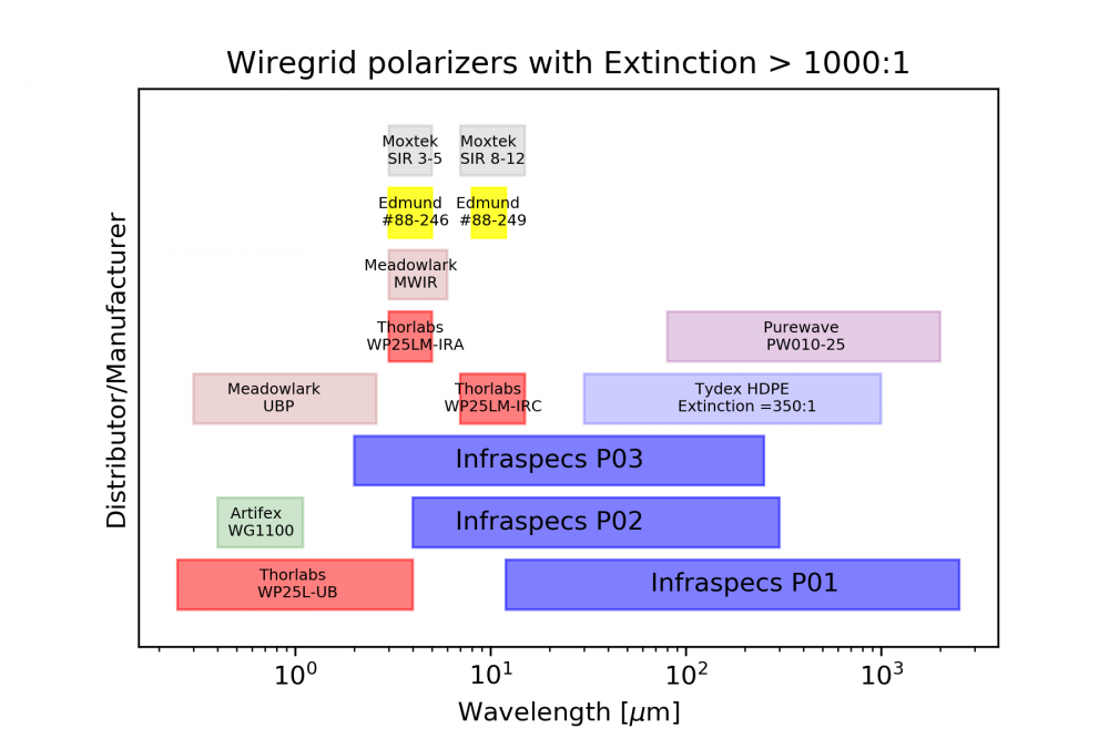
Their use is quite simple. The polarizer is placed into the beam and if the polarization state of your light was pure before, it can almost fully attenuate the beam by putting the grid lines along the polarization direction. The quality of the polarizer is measured in extinction which tells you the ratio between full transmission (two polarizers with wires set perpendicular to the incident polarization) and the crossed configuration where the wires of the first polarizer are perpendicular to the incoming radiation (transmissive) and the second polarizer's wires are along the polarization direction (no transmission). Good polarizers have an extinction of above 1:1000.
This method (although being costly) is effective in attenuating MIR beams.
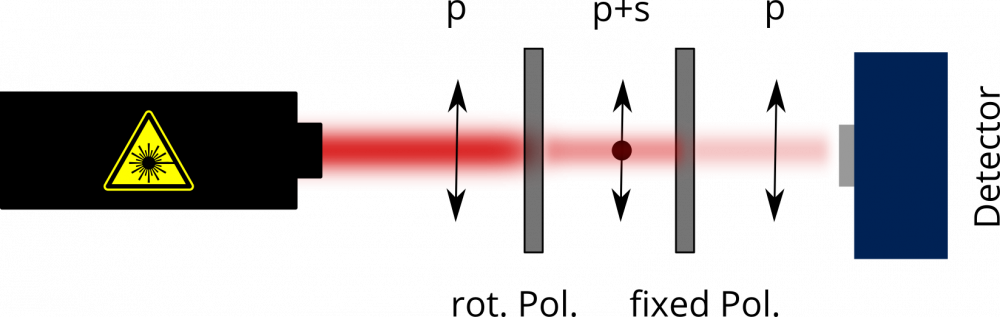
In the "two-polarizer"-configuration (figure 3) always remember that the first polarizer actually rotates the polarization. So if you set it to 45 degrees with respect to the incoming beam you have (half of the) light polarized 45 degrees with respect to the incoming beam. So with two polarizers you can also rotate the polarization by 90 degrees if you set the first polarizer at 45 degrees and the second polarizer at 90 degrees which seems a bit weird if you think about it. If your incoming beam was fully polarized you would loose 75 % of your intensity and get 25 % of the intensity polarized 90 degrees to the initial direction. This is amazing, isn't it?
Waveplate instead of polarizer
The second polarizer is usually kept fixed and defines the outgoing polarization state. The first polarizer is selecting the desired attenuation. As it is only there to change the polarization state it can be replaced by a half waveplate. A waveplate changes the polarization state according to the angle alpha between it's slow axis and the polarization by the amount of 2 x alpha. If the slow axis is 10 degrees tilted with respect to the polarization it will change the polarization state by 20 degrees. For a tilt of 22.5 degree between slow axis and the polarization state the waveplate will do a polarization rotation by 45 degrees. With a fixed polarizer behind the waveplate one can attenuate to any value exactly like with two polarizers. However, waveplates can be cheaper than polarizers but can stretch your laser pulse if it is ultrashort (i. e. in the few femtosecond regime).
The slow and fast axis of a waveplate define the biggest and smallest refractive index in that material (see Wikipedia) so that the polarization components along the slow axis travel slower (higher refractive index) than the polarization components along the fast axis (low refractive index). The difference in optical path length between slow and fast light components is chosen through material thickness such that it will be half of the wavelength (lambda/2). For half a wavelength the waveplate has to be ultra thin at visible wavelengths (true zero order waveplate). You can also make a thicker waveplate giving lets say 1000 lambda retardation as long as you put another waveplate of almost the same thickness (lets say 999,5 lambda retardation) behind it and rotate it by 90 degrees so that the fast axis of the first plate is aligned with the slow axis of the second waveplate. Some people call this a zero order waveplate also. Be aware of the trick. Sometimes you don't want this especially for broadband pulses.
Brewster's angle
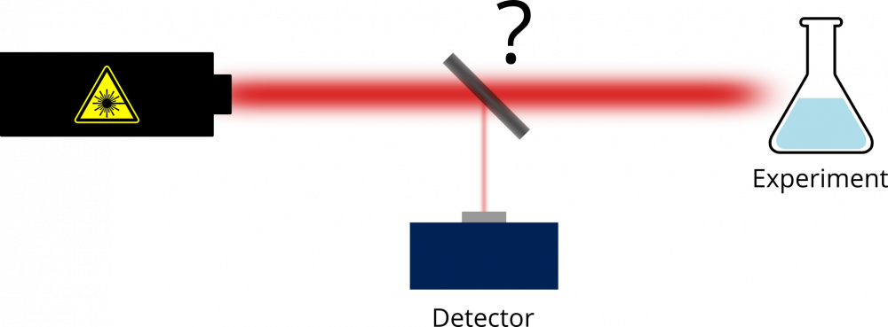
A material at Brewster's angle can be used to attenuate a polarized beam and is a quite cheap method because the only thing needed is a reflective piece of semiconductor whose bandgap is above the photon energy of your MIR radiation. In this case some radiation will be transmitted through the material and part of it will be reflected (see figure 4).
Take Silicon as an example because its easy to obtain, fairly cheap and of good optical quality. The transmission starts at 1.1 micrometer wavelength. Be aware of the dopings. For MIR and THz-applications you want highly resistive float zone grown silicon (HRFZ-Si) which is undoped and clean so it will transmit nicely. It can be obtained for example at Tydex.
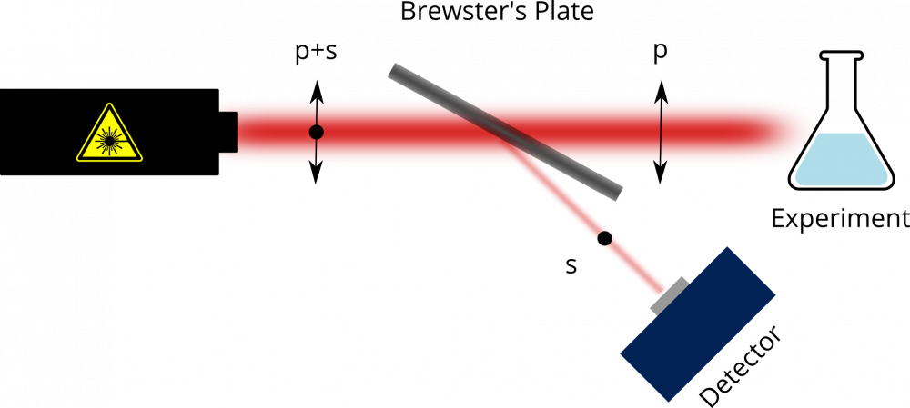
If you have a p-polarized beam, you can simply put the silicon plate in the beam and it will transmit the p-polarization as long as you have it at Brewster's angle (around 73 degree for MIR - see figure 5).
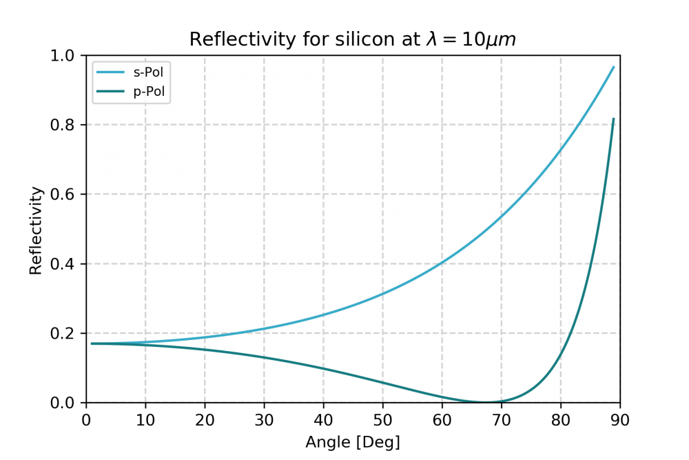
You can find exact numbers for the wavelength dependent Brewster angle for silicon and many other materials at refractiveindex.info. The Brewster angle reflection method can be used to do what is called beam sampling (just another expression for reflecting only a minor part of the beam). The minor part can be detected with one of our pyroelectric detectors (Advertisement: WiredSense MPY) and can be used to monitor your source or to do FTIR.
Unpolarized beams
Beam Sampler
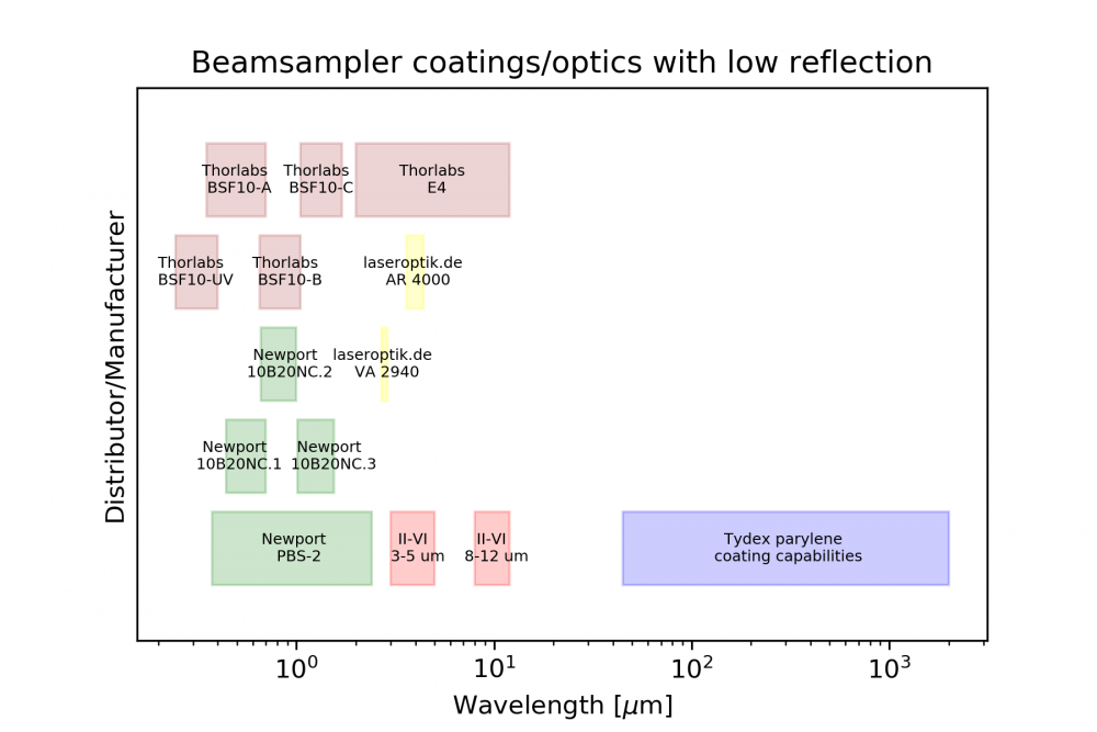
A beam sampler is a specially coated surface on a transparent material designed for a respective wavelength. The coating is made in such a way that the reflection not very high (one can call it antireflection coating). Beam samplers exist with a defined reflection for a specific wavelength of i.e. 1% or 5% or similar values that are useful for attenuation. We prepared for you a list of antireflection coated beamsamplers for the mid infrared and other wavelengths (see figure 6). The list does not mean to be complete but it might give you a hint where to start searching. As you can see in the far infrared Tydex uses parylene coatings. There are other manufacturers for parylene coatings. Tydex however can measure their performance for optics purposes. If you find promising candidates for the window between 20-40 microns, let us know. Also if you are interested in adding your products on the list, send us an email.
Find an absorber
In the MIR thick pieces of plastic can work as an absorber. Depending on your bandwidth you might select some frequencies or absorb the whole spectrum. Finding the right material and thickness can be tedious. This method seems nice but in the lab you hardly find what you need unless you bought it for that purpose. Using two wedged absorbers will allow you to control how much radiation you absorb.
Pinhole + Propagation
This technique is not ideal but may work. Depending on your beam quality you can use a pinhole or an almost closed iris to sample a small portion out of the beam. Usually it is helpful to propagate the beam a bit afterwards to reduce the influence of diffraction before you measure it (or pinhole it further down). You have to be aware that any spatial fluctuation in the beam might dramatically change the results.
Polarize and attenuate
A good way to attenuate unpolarized beams is quite obvious: Polarize it! That'll get rid of some power already but if you need to attenuate even more you can now use the methods explained in the first section.